
Engineering design and drawings of the zinc alloy die-casting process that highlight the most important aspects of the process
The determination of the pouring position, the parting surface, and the die-casting process parameters are the primary components of this document. This is followed by the drawing of the die-casting process diagram using the prescribed process symbols or text according to the specifications. The die-casting process drawing is a technical lost foam casting document that serves the purpose of guiding the process of die-casting zinc alloy. In addition to serving as the primary foundation for the acceptance of zinc alloy die-casting components, the die-casting process drawing also serves as these components' primary foundation. In this step, the location of the pouring position is established.
A zinc alloy die casting is said to be in the pouring position when it is in the mold during the pouring process. This position is referred to as the pouring position. The pouring position of the casting has a significant impact on the quality of the casting, the dimensional accuracy of the molding process, and the difficulty of the process. All of these factors are interconnected. The application of the fundamental principles that are listed below is the method that is utilized in the majority of instances to determine the location of the pouring. During the pouring process, the gas, slag in the molten metal, and sand in the mold will all float lost foam casting, which may lead to defects in the upper portion of the casting. These defects may include pores, slag inclusions, and blisters. The lower portion of the casting, on the other hand, has a denser structure and is less likely to have defects than the upper portion of the casting. According to the illustration, the machine tool bed ought to be positioned so that the guide rail is facing downward when it is in the pouring position. Performing this action is done in order to guarantee that the quality of this crucial working surface is preserved.
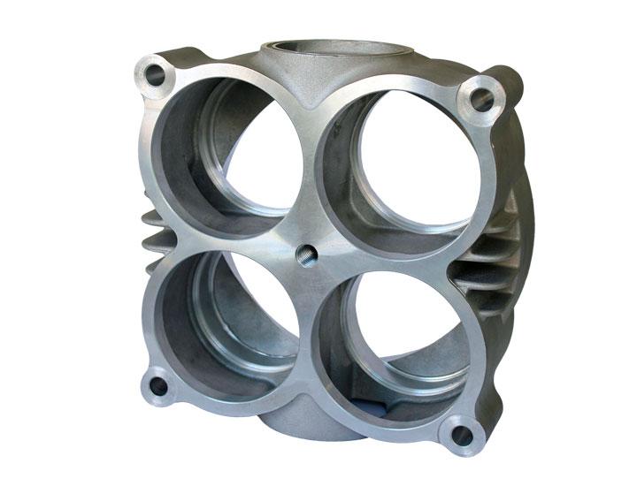
The illustration makes it abundantly clear that the requirements for the quality of the circumferential surface of the winch are relatively high.

In the second step, the large flat surface of the casting is poured in a direction that is either tilted or below the horizontal. The hot, molten metal releases a significant amount of heat into the upper portion of the mold while the pouring process is being carried out. As a consequence of this, the top surface of the molding sand will expand, arch, or even crack, which will lead to defects such as sand inclusions and blisters appearing on the large surface. In order to avoid casting defects on large surfaces, it is possible to either position the large surface in a downward direction or use an inclined pouring method. Both of these options are viable options. It is suggested that the thin wall that has a larger area be positioned at the lower part of the casting, or that it be positioned in a side wall or inclined position. Both of these options are recommended. In this way, the casting's thin-walled components will be protected from the cold insulation and poor pouring defects that could otherwise occur. Make it simpler to position risers in dense areas specifically for the purpose of feeding. This is the primary goal of this project. For the purpose of parting, the selection of the surface
One of the surfaces that is referred to as the parting surface is the joint surface that is present between the components of the mold. For the purpose of simplifying the process of mold removal, it is common practice to select the parting surface that is located in the center of the casting's largest cross-section. In order to discover the surface of the parting, it is essential to adhere to the principles that are described in the following paragraphs.
It is recommended that the parting surface be selected at the point where the pattern's cross-section is the largest. This preference is made with the intention of making mold removal more straightforward. When the number of parting surfaces is reduced, it becomes much easier to ensure that the castings are accurate and to streamline the process of molding. The majority of the time, when it comes to machine modeling Ductile Cast Iron, there is only one parting surface present. Regarding the production of single pieces and manual molding, it is reasonable to have two parting surfaces. This is because of the nature of the production process. This action is taken in order to cut down on the quantity of tooling that is produced.
The fourth step is to make an effort to save as many of the castings as you can within the same sand box. When the castings are placed in the same sand box, not only does this make it simpler to match the molds, but it also helps to prevent the molds from becoming misaligned, which is another factor that contributes to the accuracy of the castings.
Make an effort to keep the core in the lower box, and pay close attention to ensuring that the height of the sand box is as low as it can possibly be. Because of this, the process of molding can be simplified, core setting and molding can be made easier, and mold removal and molding can be made easier. All of these things can be made easier.
There are a number of factors that are associated with the machining allowance, which is dependent on the level of accuracy of the casting. These factors include the casting material, the casting method, the production batch, the casting size, the pouring position, and so on.
Following the determination of the tolerance level and the machining allowance level of the casting, the value of the machining casting services allowance can be chosen in accordance with GB/T11350-1989, and the value of the tolerance can be chosen in accordance with GB6414-86. Both of these choices are possible. In order to simplify the casting process, it is possible to machine the small holes and grooves that are present on the castings rather than casting them. This would allow for the casting process to be conducted more efficiently.
The angle of the draught
Angle of the DraftThe term "draft angle" refers to the slope of the wall on the pattern that is parallel to the direction in which the draft is moving Ductile Cast Iron. This angle can be expressed as either the width a or the angle α, depending on the context. The application of this angle is done with the intention of making the pattern more straightforward to remove from the mold. The use of width a is strongly recommended for you to consider. It is possible to determine the draft angle of the pattern by either increasing the wall thickness, adding or subtracting the wall thickness, or decreasing the wall thickness. Each and every one of these distinct approaches is feasible.
In accordance with the standards that are applicable, there is the possibility of selecting the necessary increase or decrease in the draft angle. When clay sand modeling is utilized, the determination of the draft angle casting services can be accomplished through the application of the JB/T5105-1991 standard. Molds that are usually made of wood have a slope that ranges from 0.6 to 3.0 millimeters, whereas molds that are made of metal have a slope that ranges from 0.4 to 2.4 millimeters. When the ratio of the height to the diameter of the hole in the casting is less than one (H/D is less than 1), it is possible to cast the hole using a core that is enclosed within itself. This is the case in situations where the distance between the two dimensions is less than one.
The rate at which the object is shrinking
The size of the pattern needs to be increased in order to make the cooled casting conform to the specifications of the drawing and to compensate for the shrinkage of the casting that occurs during the cooling process. Both tasks are accomplished by increasing the size of the pattern. By casting the sand mold with round corners, it is possible to lessen or eliminate the risk of incurring damage to the sharp corners of the mold. In addition, this may prevent sand from adhering to the surface, cavities caused by shrinkage, and cracks from appearing. The corners of the casting parting surface, on the other hand, must not have any rounded corners at any point under any circumstances. what is depicted in the picture is clear. Specifically, the core seat is the cavity in the mold that is designated for the placement of the core head. This cavity is found in the mold. Due to the fact that the values are connected to the length (height) and diameter of the core, it is essential to consult them. After the information has been verified, the information should be confirmed.